Posted: January 22, 2016
 One key aspect of the energy and cost optimisation of large-scale collector fields (called arrays in this news) is collector array hydraulics. Optimal connection is achieved when (1) the costs and length of the connecting pipes is small, (2) the pressure drop over the entire array is low and (3) there is homogeneous mass flow distribution across the entire field. “Homogeneous mass flow reduces power losses in the circuit, avoids inefficient pump operation and prevents local stagnation,” explains Philip Ohnewein. The researcher at Austrian institute AEE INTEC managed the four-year project ParaSol (2011 to 2014), which – among other things – analysed the advantages and disadvantages of different hydraulic designs of large collector arrays of several hundreds to several thousands of panels. The results were also discussed and published as part of Task 45, Large Systems: Large Solar Heating/Cooling Systems, Seasonal Storage, Heat Pumps, of the IEA Solar Heating and Cooling Programme in a two-page info leaflet and a 44-page technical document.
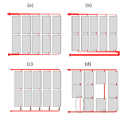
The chart above shows the four methods to achieve optimal hydraulic behaviour in large-scale solar plants with flat plate collectors:
(a) Adjustment of supply and return pipe diameters: the simplest passive hydraulic adjustment, allowing cost savings in the collector array’s piping
(b) Tichelmann connection in combination with adjustments to pipe diameters: a proactive measure with the disadvantage of increased costs because of greater pipe length
(c) Installation of mechanical balancing valves: very effective measure for homogenous mass flow, but costly and a potential source of errors
(d) Adjustment of collector connecting pipe diameters: low-cost measure for adapting the piping to various external conditions; based on simulations in design phase, but with high costs in case of adjustments during operation.
11 indicators to help determine performance of hydraulic schemes
“To facilitate a direct comparison of different hydraulic concepts, we developed a set of 11 indicators which can be calculated in a theoretic analysis at the design phase of a plant and allow for a more sophisticated and more economic collector array design,” explains Ohnewein. The AEE INTEC team used the new indicator set to analyse different solar hydraulic configurations. The description of all 11 indicators can be found in the ParaSol conference paper of SHC 2013 in English and in the final ParaSol report in German.
Comparing harp- and meander-type collectors
The following table shows the indicators which differ significantly when a 4,800 m2 collector field is set up either with harp-type or meander-type absorbers, despite the gross collector area, the specific mass flow and the solar yield being almost identical in both cases. In four of five categories, the meander-type collector field outperforms the harp-type collector one; only copper demand is greater for the former (see the following table). “The differences between harp- and meander-type arrays regarding technical behaviour, cost and design aspects is more obvious in fields with collector areas in a single row above 300 m2”, explains Ohnewein.
|
Collector array key figures
|
Large-scale, harp-type collector field with 4,800 m2
|
Large-scale, meander-type collector field with 4,800 m2
|
Notes
|
|
Specific metal mass of array pipes
|
0.84 kgsteel/m²gr
|
0.50 kgsteel/m²br
|
Relevant to material costs
|
|
Pipe network length
|
~6.3 cm/m²gr
|
~2.1 cm/m²gr
|
Relevant to excavation costs
|
|
Specific copper mass in solar collector
|
1.28 kgCu/m²gr
|
1.96 kgCu/m²gr
|
Relevant to collector production costs
|
|
Thermal capacity of collector array
|
11.3 kJ/m²br·K
|
9.6 kJ/m²br·K
|
Relevant to start-up losses
|
|
Ratio of hydraulic to thermal power
|
1.37 Whydraulic/kWth
|
1.27 Whydraulic/kWth
|
Relevant to pump electricity consumption
|
List of indicators which differ between collector fields with harp- type and meander-type collectors. All indicators have been calculated by using simulation programme SOLAR, which was developed by AEE INTEC.
Lower mass flow compensates for low irradiation
The researchers from AEE INTEC also wanted to find out whether reducing the mass flow in the collector array can compensate for periods with low irradiation and low ambient temperatures. “Our simulation showed that a collector field can still operate worthwhile at a radiation of 400 to 500 W/m2, if mass flow is significantly reduced from around 12 kg/m2 to 3 kg/m2abs per hour,” Ohnewein explains the results.
Mechanical balancing valves in each collector row
The advantages of mechanical balancing valves in each collector raw were examined for the following plant: a 6,000 m2 collector field consisting of rows with 4 to 11 collectors each, because of plot size. The valves reduce the maximum absorber temperature in the field, minimise pressure losses significantly and cut the pumps’ hydraulic power in half.
|
|
Without regulating valves in each row
|
With regulating valves in each row
|
|
|
Specific yield per gross collector area
|
429
|
432
|
W/m²
|
|
Outlet temperature of the collector array
|
85.0
|
85.3
|
°C
|
|
Maximum absorber temperature
|
100.7
|
86.0
|
°C
|
|
Pressure drop of entire collector array (excluding supply pipes)
|
730
|
380
|
mbar
|
|
Hydraulic power for the entire array
|
1,056
|
557
|
Whyd
|
Simulation results of a collector field with and without regulating valves for each array
Source: AEE INTEC
Fact sheets for download on programme`s website
Besides the analysis of different hydraulic schemes, the Task 45 experts have examined the performance of different seasonal storage units, developed a methodology for performance guarantees regarding large-fields and published case studies on successful third-party financing, for example, in the form of Energy Service Companies (ESCOs). A set of fact sheets on different aspects is available for download on the task´s website: http://task45.iea-shc.org/fact-sheets.
More information:
For further information about ParaSol contact Philipp Ohnewein: p.ohnewein@aee.at